Installation Procedure
INSTALLATION PROCEDURE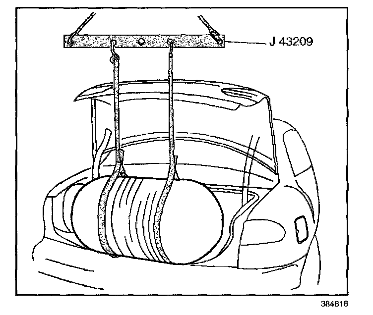
1. Install a NEW O-ring on the HPL
2. Lubricate the O-ring with petroleum jelly.
3. Install the HPL in the tank and tighten hand-tight.
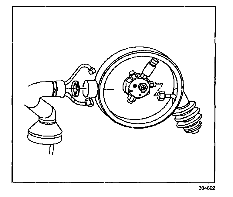
4. Lower the tank onto the J 43133 using a lifting device and the J 42309-B.
5. Roll the tank to the proper position using the orientation marks.
6. Raise the J 43133 and roll the tank into the tank cradle.
7. Remove the J 43133 from the tank bracket.
8. Install the tank straps.
9. Install the tank strap bridge pins and clevis pins.
NOTE: Refer to Fastener Notice in Service Precautions.
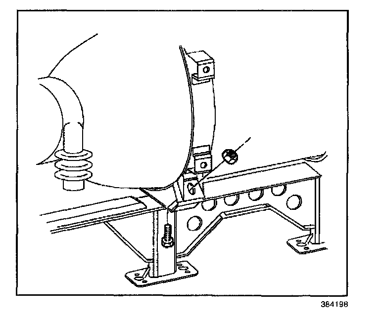
10. Install the OLD tank strap nuts and bolts.
Tighten
Tighten the OLD tank strap nuts to 48 N.m (35 lb ft).
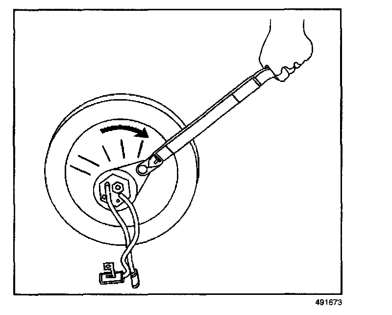
11. Tighten the HPL as specified below.
Tighten
Tighten the HPL to a nominal torque of 305 N.m (225 ft lb) at 0 degree. You must compensate for your torque wrench and the HPL crowfoot. Refer to the formula below for compensation of your torque wrench.
IMPORTANT: Ensure the J 43602 HPL Crowfoot removal tool is straight (0 degree) on the torque wrench
12. To obtain your Dial reading perform the following:
^ Multiply your torque wrench length in inches by 305. 18 inch torque wrench example: 18 X 305 = 5490
^ Add three to the length of your torque wrench. 18 inch torque wrench example: 18 + 3 = 21.
^ Divide the first value obtained by the second value obtained. The result will indicate the amount of torque your wrench should tighten the HPL to. 18 inch torque wrench example: 5490 divided by 21 = 261.4.
For an 18 inch long torque wrench you would tighten the HPL to 261.4 N.m.
13. Remove the OLD tank strap nuts and bolts and discard them.
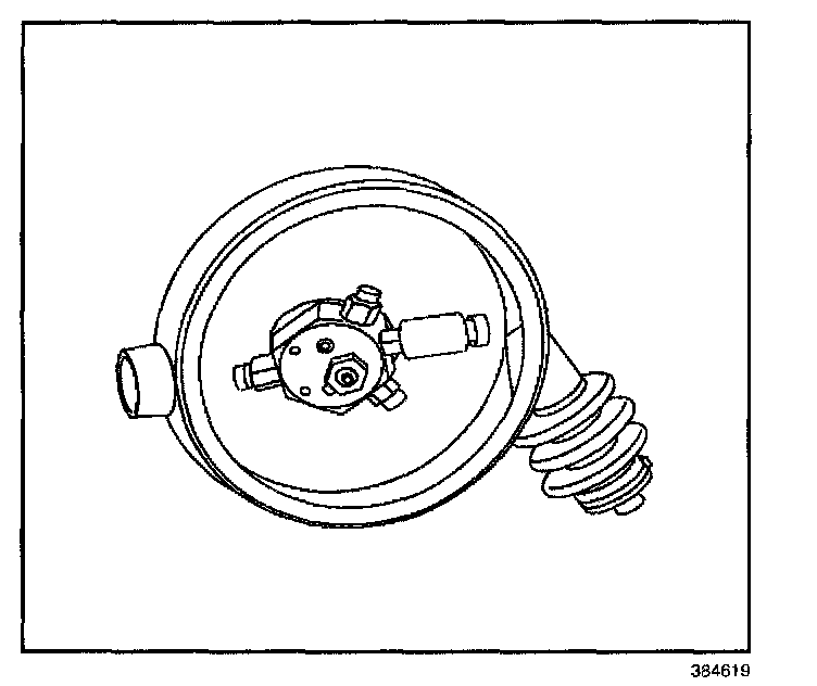
14. Verify the alignment of the HPL inlet port. The fitting should be at the 3 o'clock position. Adjust the tank as necessary.
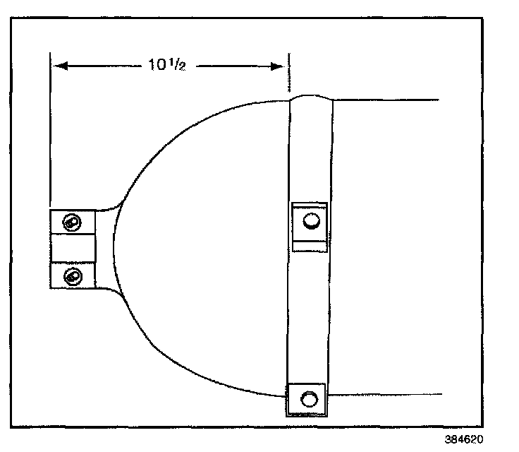
15. The tank should be located 26.7 cm (10.5 in) from the left edge of the left tank strap. Adjust the tank as necessary.
16. Install NEW tank strap bolts and nuts.
Tighten
Tighten the tank strap nuts to 48 N.m (35 lb ft).
17. Install the vent boot.
Tighten
Tighten the vent boot clamp to 2 N.m (18 lb in).
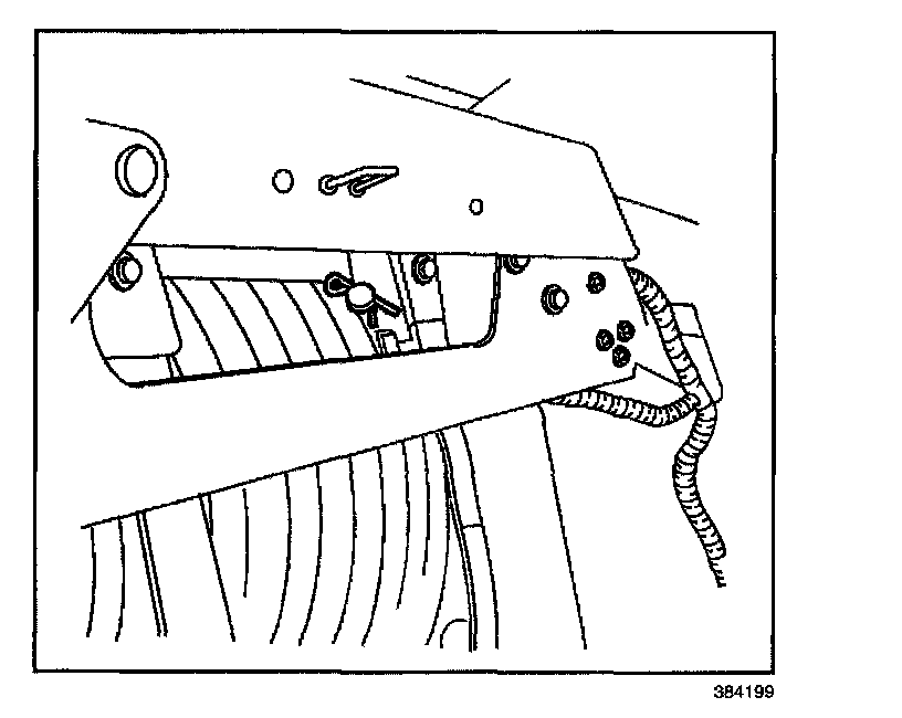
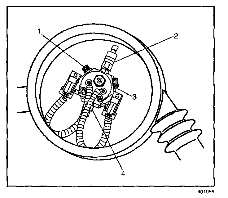
18. Install the fuel outlet fitting (1) into the HPL using a NEW O-ring. Lubricate the O-ring with petroleum jelly.
Tighten
Tighten the fitting to 27 N.m (20 lb ft).
19. Install the fuel inlet fitting (3) into the HPL using a NEW O-ring. Lubricate the O-ring with petroleum jelly.
Tighten
Tighten the fitting to 48 N.m (35 lb ft).
20. Install the FPS (2) into the HPL using a NEW O-ring. Lubricate the O-ring with petroleum jelly.
Tighten
Tighten the fitting to 27 N.m (20 lb ft).
21. Install the Pressure Relief Device fitting (4) into the HPL using a NEW O-ring. Lubricate the O-ring with petroleum jelly.
Tighten
Tighten the fitting to 48 N.m (35 lb ft).
22. Install the Pressure Relief Device line and the HPL to HPR lines as an assembly.
23. Connect the Pressure Relief Device and HPL to HPR lines using NEW O-ring face seals. Lubricate the O-rings with petroleum jelly.
Tighten
Tighten the Pressure Relief Device line fitting to 37 N.m (27 lb ft)
Tighten
Tighten the HPL to HPR fuel line fittings to 24 N.m (18 lb ft).
24. Install the fill valve to union fill line using NEW O-ring face seals. Lubricate the O-rings with petroleum jelly.
Tighten
Tighten the fill line fittings to 37 N.m (27 lb ft).
25. Install the union to HPL fill line using NEW O-ring face seals. Lubricate the O-rings with petroleum jelly.
Tighten
Tighten the fill line fittings to 37 N.m (27 lb ft).
CAUTION: The high pressure lock-off solenoid seal Is more likely to leak at a lower fuel pressure. Always perform the fuel leak procedure exactly as specified Failure to follow the proper procedures may result in serious injury or damage to the vehicle or part.
26. Fuel the vehicle in three stages at the following pressures:
26.1. 500 psi
26.2. 1500 psi
26.3. 3000 psi
27. Using the J 41416, inspect for fuel leaks at the HPL at EACH pressure.
28. Connect the electrical connectors and the HPL power connector.
29. Connect the negative battery cable.
30. Start and operate the engine on CNG.
31. Inspect for fuel leaks at each serviced fitting using the J 41416
32. Position the four hose clamps at the vent boot, the vent hose and the fill valve boot.
Tighten
Tighten the hose clamps to 2 N.m (18 lb in).
33. Install the vent boot cover using NEW cover nuts.
Tighten
Tighten the NEW vent boot cover nuts to 6 N.m (54 lb in).
34. Install the left side trunk carpet.
35. Install the cargo net knobs and the cargo net.
36. Install the trunk trim.
37. Attach the information label supplied with the replacement HPL in a visible location on the head of the tank.
38. Install the spare tire bracket and spare tire bracket bolts.
Tighten
Tighten the spare tire bracket bolts to 27 N.m (20 lb ft).
39. Install the tank cover.